(You would almost certainly not use the Radar or Sonar spins under this heading)
-
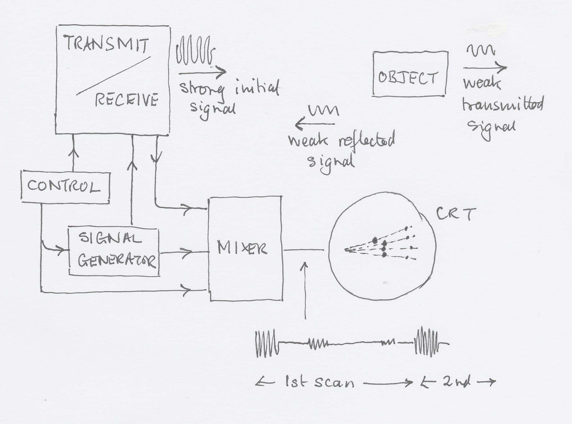
A pulse of carrier wave is dispatched at intervals determined by the clock.
-
The energy will spread out (inverse square law) and be partially absorbed by the medium. These diminutions in signal strength must be taken into account.
-
A portion of the energy will be reflected by any discontinuities that exist on a line from the transmitter perpendicular to its aperture. The return time and strength will be noted by the system.
-
The next pulse will be dispatched in a different direction (perhaps by using a rotating aerial, or perhaps by using an array of emitters and introducing a progressive phase shift into the signals supplied to them so as to do a kind of diffraction grating in reverse) so as to return information about discontinuities in a different part of space.
-
A CRT has an electron beam making a sweep under the control of the timebase, which is synchronised to start just as the pulse starts its journey.
-
The mixed signal is fed to the grid of the CRT so as to affect the brightness of the trace. Reflected signals cause an increase of brightness.
-
The timebase is organised to sweep the beam across the screen in a direction related to the direction in which the signal is transmitted. In this way a map is built up.
Radar
The transducer is a radio aerial, often letterbox-shaped so as to give a wide diffraction pattern vertically and a narrow pattern horizontally (remember that pattern width varies inversely with slit width). Since the resulting image is a map, this gives good resolution in the plane of the map while ensuring that everything in a vertical direction is picked up.
Ultrasound
The transducer is a piezo-electric crystal, which vibrates when a pd is applied across it (and vice-versa).
Sonar
The transducer is a piezo-electric crystal, which vibrates when a pd is applied across it (and vice-versa). I don't think you sweep through different angles with sonar, but I'm not going to take the time off to look just at the moment.
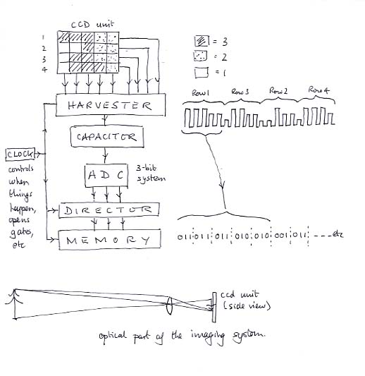
Suitable for CCTV cameras, camcorders, infra-red cameras, etc.
-
A CCD chip consists of an array of independent photodiodes, each one constituting a pixel.
-
Incident radiation (visible or I.R.) releases a number of electrons on a given pixel proportional to the strength of the radiation and how long it is on for.
-
Periodically the charges are harvested onto a capacitor that develops a voltage proportional to the charge and therefore to the radiation intensity. This potential is converted to binary by an ADC and the value stored in a memory chip.
-
Control circuitry sees to it that a particular memory location always stores the information about the radiation intensity on a particular pixel. The circuitry polls the pixels in order across the chip and then moves down to the next row but one, and so on, scanning every other row. Then it goes back and does the intermediate rows. It mustn't stop, because the charge accumulated is proportional to the elapsed time as well as the intensity.