Diffraction
We have studied a number of effects independently (single slit diffraction, Young's slits and diffraction gratings) and you will be aware of reflection gratings and the fact of the blue sky being caused by the scattering of light in the atmosphere. I think the best thing is to try to synthesis all these ideas into some generalities from which you can then respond to any particular manifestation of the effect. So these notes are distinctly for someone who already knows about the particular examples.
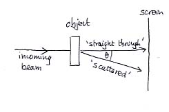
When we draw a line like that labelled 'scattered' we don't necessarily imply that a beam exists in that direction: it is merely a direction of interest, and it may turn out that a beam does not emerge.
The various beams will hit the screen and we will see patches of the screen where there is plenty of signal and patches where there is less. We are interested in the intensity and position of signals on the screen. The patches are often known as 'fringes'. We usually use the 'straight through' beam as the reference point both for angular measurement and for fringe position measurement.
The angle q is the central parameter that binds everything together. Determining the fringe separation at the screen is then just a scaling exercise that incorporates the distance between screen and object.
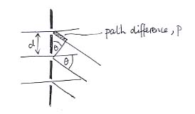
p = d sin q
Notice once again that there may not in fact be a beam in the direction q : the path difference is just a geometrical thing.
Notice also that if the path difference is obliged to be constant for any particular effect to occur, then increasing d will decrease q , and vice versa.
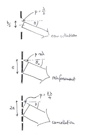
(b/2) sin q (geometry) = p = l /2 (optical condition)
So b sin q = l gives the condition for no beam to emerge from a slit, and most of the energy is constrained to appear in between the boundaries defined by this angle on each side of the 'straight through' position.
The second diagram relates to Young's slits, and leads to the equation
e sin q n (geometry) = p = nl (optical condition)
The last diagram relates to a four-slit grating. It shows how, if the path difference for two adjacent slits is ¾l then the path difference between slits 1 and 3 will be one and a half wavelengths, leading to cancellation. Since slits 2 and 4 will cancel by the same token, this angle will be one in which no beam emerges. A similar argument applies if padjacent is ¼l or ½l. So there will be three 'no beam' angles between the 'straight through' position and the esinq = l condition for brightness.
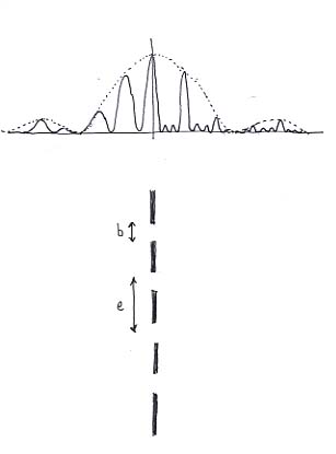
Look first at the left hand half of the graph and imagine that the right hand half were just a reflection of the left hand half. This shows the intensity of light you would get if you just used two of the slits shown in the lower part of the diagram (in other words, the Young's slits experiment). Notice the dotted-line single slit pattern, governed by the individual slit widths b. b, the smallest feature of the object governs the biggest feature of the output. Notice the half-width side maxima of this overall shape.
Notice next the equally spaced fringes whose position is governed by the slit spacing e and whose height (intensity) is determined by whether or not light is emitted in those directions by the individual slits in the first place.
Notice finally that b is about two fifths of e and that about 2½ fringes fit into the space between the straight through position and the single slit diffraction minimum.
Now concentrate on the right hand portion of the graph and imagine that the left hand portion is a mirror image. This is the graph you would get if you used all four of the slits shown. Notice that the overall single slit envelope has not changed because b is still the same. Notice that the fringe separation has not changed because e is still the same.
But, now that we have four slits, three 'zero' angles exist between the fringe maxima, and this crowds all the energy into much narrower angular bands around the maxima. So the fringes are much sharper and can more easily separate out different colours - the resolution has improved. Notice that this smallest feature of the output has been determined by the largest-scale feature of the object : its overall width. (Observe, too, that doubling the number of slits has doubled the energy reaching the screen, and each fringe is now half the width it was. So our vertical axis should really be four times as high.)