Communication
Communication is about transferring information from one place to another via one or more intermediate systems. Here are some examples
| Semaphore | Thought in Jack's mind | à | Position of two flags | à | Light reflected off flags | à | Image on Jill's retina | à | Thought in Jill's mind |
| Walkie-talkie | Speech | à | Voltage (via microphone) | à | Radio wave | à | Voltage in receiver | à | Sound (via earpiece) |
| Outside broadcast | Football match | à | Voltages (via video camera) | à | UHF wave | à | Voltage in receiver | à | Picture on Cathode Ray tube |
| Song | Concert | à | Digital recorder | à | CD | à | Voltage in player | à | Sound via loudspeaker |
It helps (but is not essential) to have some vocabulary. Things in coloured boxes are often called signals. Boxes with light outlines are electrical signals and boxes with black outlines indicate electromagnetic signals, although there are no hard and fast rules about when to use these terms. Things not in coloured boxes are sometimes called stimuli. Devices which convert stimuli to signals and vice versa or which convert one kind of signal into another are often called transducers. We'll discuss transducers later.
Sometimes it is appropriate to use the term analogue. This means, roughly, that something can have any value you like. 'Continuous' or 'smoothly varying' are other terms sometimes used here. The opposite is discrete or pixelated, which involves making sudden jumps ('digital' means something else, which will be dealt with shortly). For example:
in the walkie-talkie case, the pressure waves arriving at the microphone and voltage signal produced by the microphone are both analogue: the person can make sound of any pitch or volume he chooses (within limits).
in the football match case, although the scene itself is continuous and analogue, it gets split up in the camera into a number of tiny rectangles called 'pixels', each of which is the same colour all over. The apparent smooth change between dark and light in some parts of the picture is an optical illusion to do with the limitations of the eye. When the picture is reconstructed on the CRT (Cathode Ray Tube) there is a further issue. On a monochrome screen, each pixel can vary continuously (analogue) to be any brightness (you can verify this possibility by twiddling the brightness control on an ordinary CRO). But on a colour monitor the brightnessof the red component, say, has to be one of just 256 different levels. So there are two elements of discreteness (non-analogue) here: splitting the stimulus up into chunks and then only being allowed particular values for those chunks.
in the case of the song, the music is recorded as a sequence of pits in the surface of the CD. This forms a 'signal waiting to happen', and it gets transported around the country in lorries before being sold. The communication process only continues when the CD is inserted into a player.
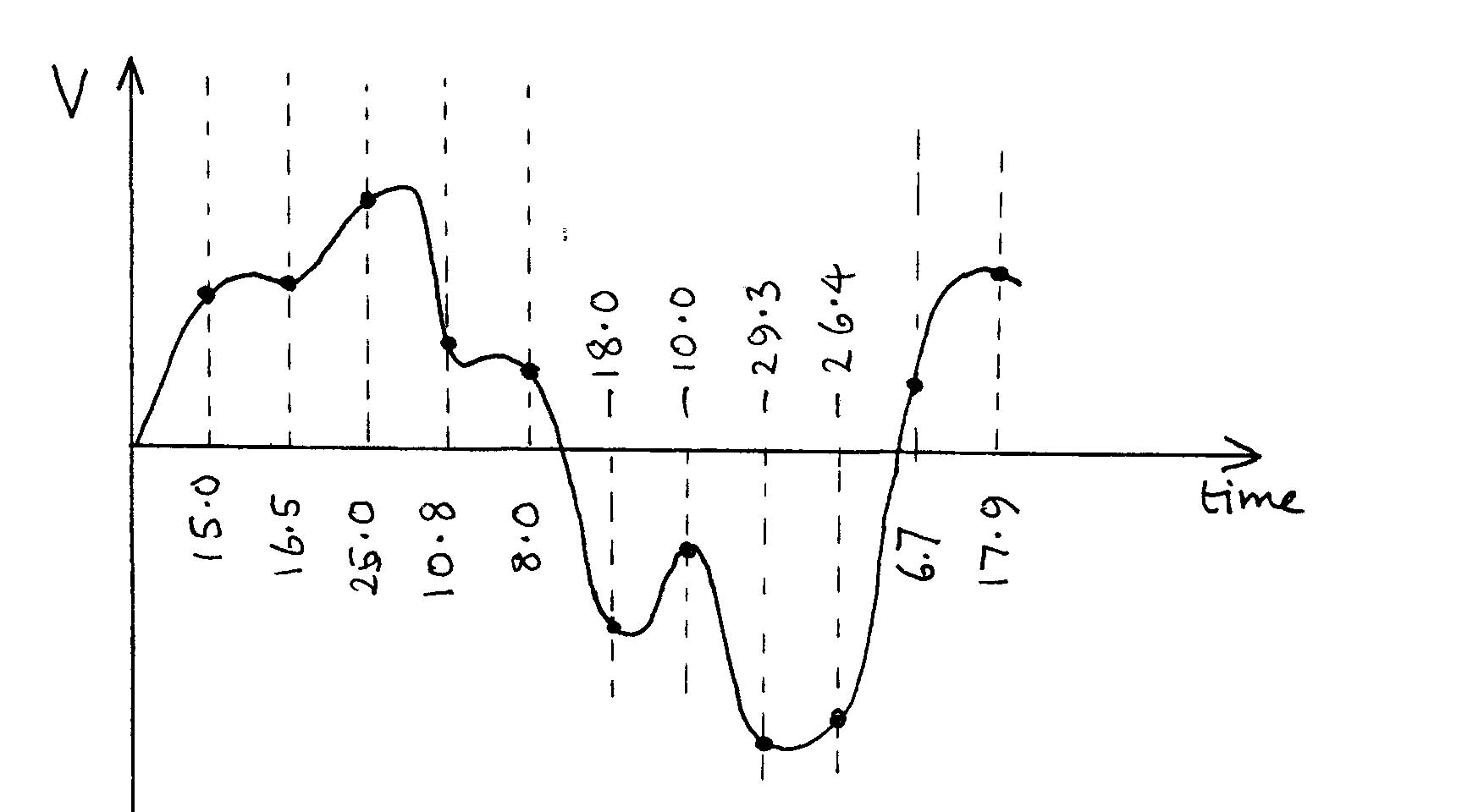
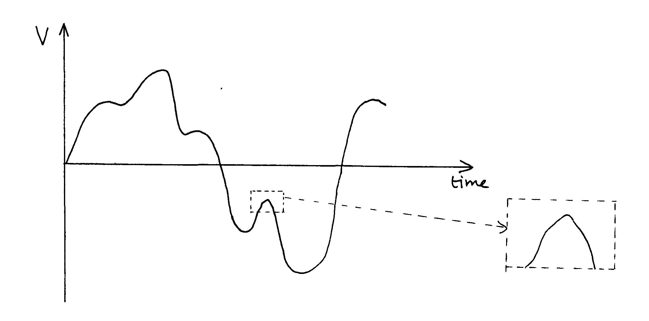
Here is a picture of the initial pressure wave you might get in the song case. The voltage signal produced by the microphone will have the same shape (and indeed the vertical axis has been thus labelled).
The wave is analogue, in the sense that if you zoom in on a portion of it (as shown by the dotted boxes) the enlarged picture is still continuous (although if you zoom in on the computerised version you are looking at on-screen the curves will eventually turn into a discrete step-like structures).
The first move
away from this analogue signal is to sample it by just looking at
the V value every now and again.
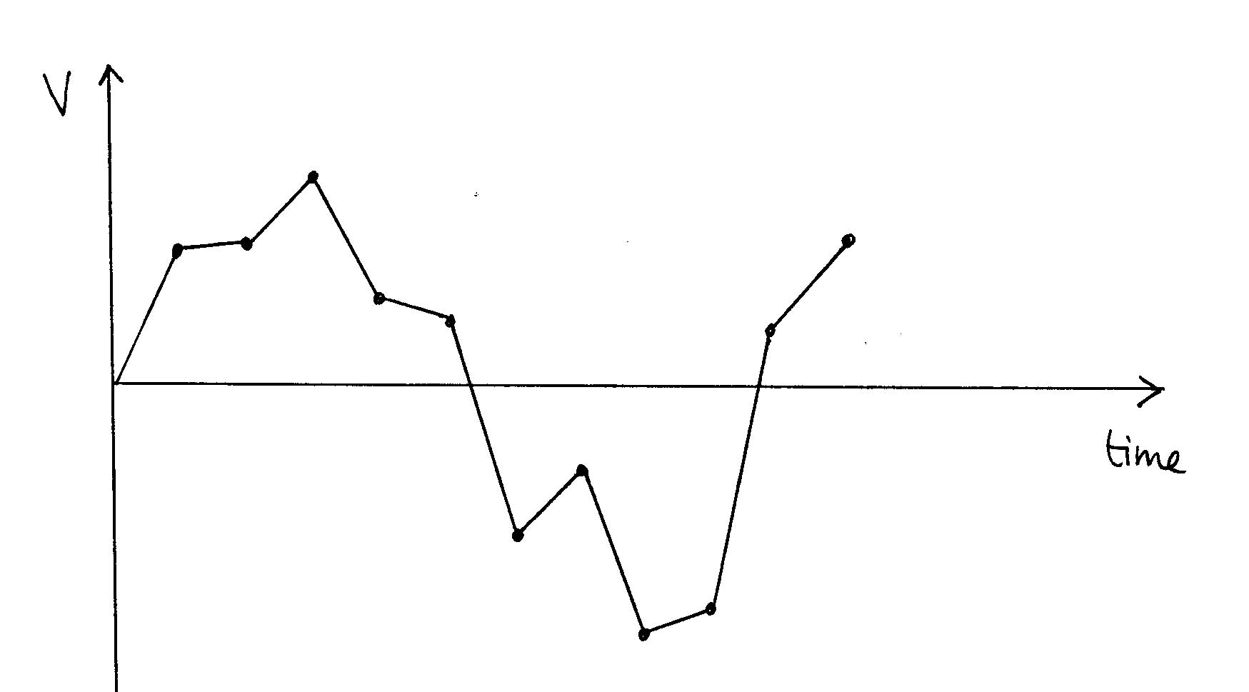
In the right-hand diagram vertical dotted lines have been drawn and, below them, the vertical distances of the spots from the time axis, measure in millimetres on the original of the graph, and expressed to the nearest 0.1 mm. In the right-hand diagram spots have been drawn at those heights and then joined. If you simply read the numbers out to a friend on the other end of a telephone, that's the graph he would draw. Well, he might do a best fit curve, and that would be a slight improvement, but you would still have lost the wiggle between the 4th and 5th points, for example. In CD recording, samples are taken just over 44,000 times a second - that's more than twice the highest frequency that humans can detect (about 20 kHz), so the fidelity is potentially good enough for listeners not to notice that the 100% accurate analogue signal has been replaced. |
||
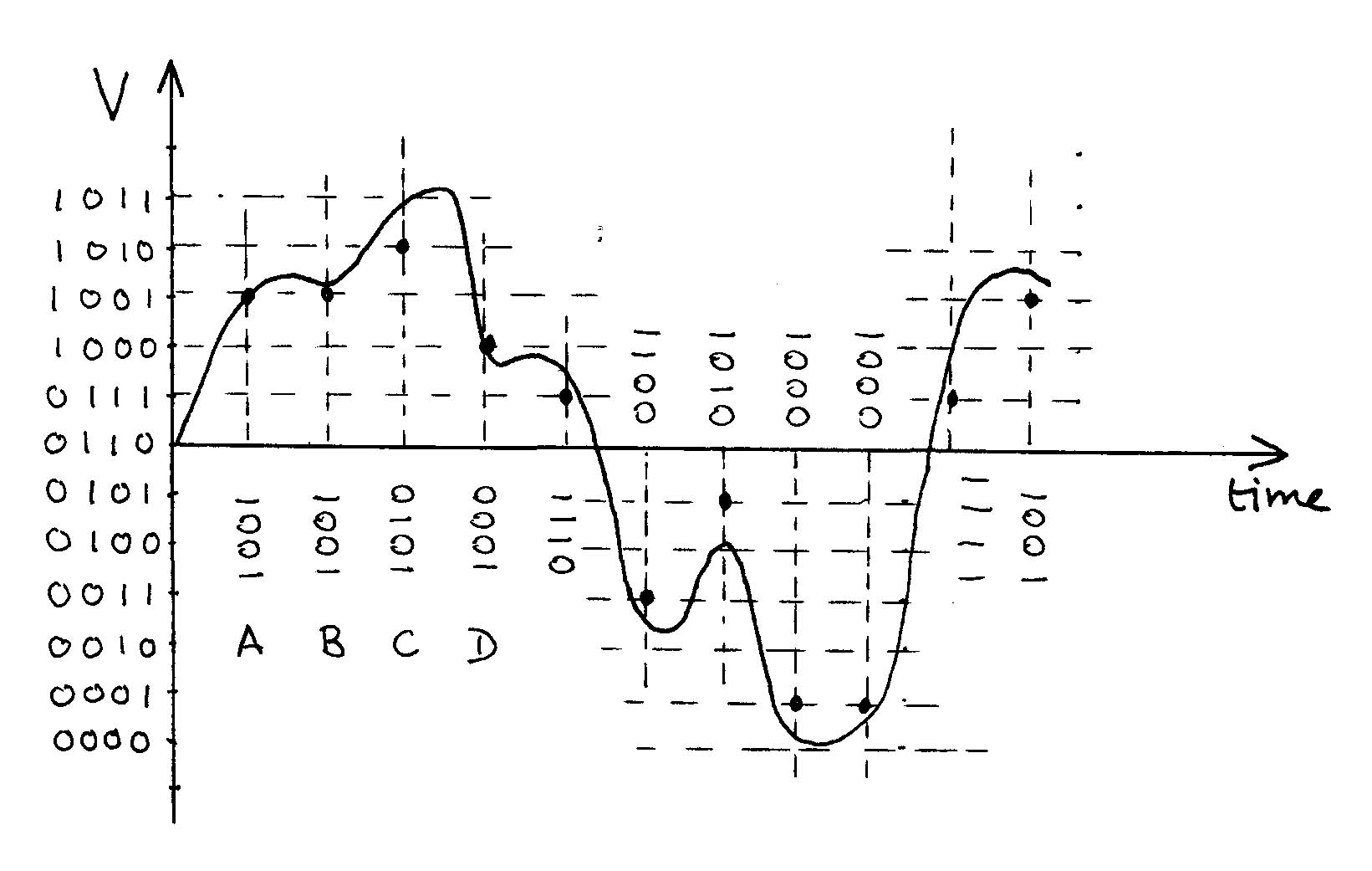
The next move away
from fidelity is to limit the number of values that the sampled voltage
can take.
In the left-hand diagram the wave has been sampled at the same times as before, but dots have only been put at a limited number of horizontal levels, choosing each time the nearest level between the wave and the time axis. The levels have been coded with a four-bit binary code. There are only 12 levels here, but a four-bit code can cope with up to 16 levels (24 =16). CD recording uses a 24-bit code, which gives about a billion different levels, which allows quite a good approximation to the analogue original when it comes to the reconstruction. |
||
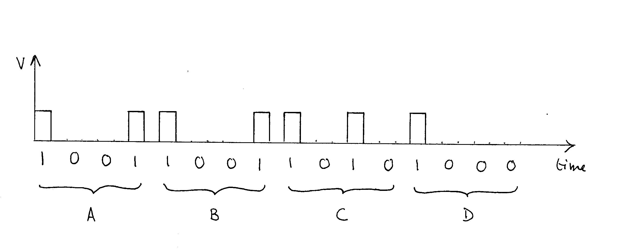
| The final stage of
encoding the signal is to string the various 4-bit codes together and
represent 1s with a high voltage and 0s with a zero voltage
The portion shown here only deals with the first four samples of the original wave, labelled A, B, C and D. At this stage the signal is said to be digitised. A digital signal is one that consists of just two voltages, the exact moments of high and low carrying the coded information from which an approximation to the original signal can be re-constructed. |
Pros and Cons of analogue and digital
| The major advantage of analogue
is its absolute fidelity to the original (in theory). Its major
disadvantage is its corruptibility. Consider, for example, an
old-fashioned vinyl disc, which has a wiggly groove scratched into its
surface. A stylus placed in the groove can be made to vibrate in exactly
the same way as the groove wiggles, and this vibration can be turned
into a continuously varying analogue voltage. But the system cannot
distinguish between stylus movement caused by the groove and movement
caused by a stray bit of grit in the groove or a surface imperfection,
so these defects will cause the sound be different on playback. Similarly, stray changing magnetic fields, such as those produced by working electric motors or just by the AC mains working, can induce e.m.fs in the wire carrying the signal, and the system will have no way of knowing whether the voltage is supposed to be 6.4 V, say, or whether it's really 5.9 V with 0.5 V of stray induced e.m.f. On the other hand a digital signal is relatively immune to 'noise' of this type. Suppose the two voltages being used are 0 V and 6 V. Anything above 3V the system will count as high and anything below it will count as low. So if one of the pulses is 7 V rather than 6 V because of an induced e.m.f. of 1 V, the system will still treat it as high and the coding is unchanged. Similarly if a 1 V induced e.m.f. finds its way onto a wire that is supposed to be carrying a 'low' signal, the system will still interpret the 1 V as low, and no fidelity will be lost. Furthermore, digital signals lend themselves to being finally coded as a sequence of on-off light signals. These can be conveyed down optical fibres which, being non-conducting, are absolutely impervious to corruption by any electromagnetic interference.
|