Potential dividers

A chain of resistors

(In all that follows, the numbers have been chosen to make calculations easy. You should take the trouble to check that you agree with each numerical statement.)

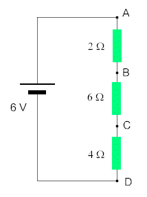
The total resistance of the circuit on the left is 12 W.

This means that the current flowing is 0.5 A.

The p.d. across the top resistor is 1 V (using V = I R). This is one sixth of the total p.d. available. Furthermore, the resistance of the top resistor (2 W) is one sixth of the total resistance available (12 W).

The p.d. across the middle resistor is 3 V (using V = I R). This is a half of the total p.d. available. Furthermore, the resistance of the middle resistor (6 W) is a half of the total resistance available (12 W).

So the general rule is that  the pd across a resistor is the same fraction of the total pd as the resistance is of the total resistance. Check that this rule works for the bottom resistor.

If we decide that the potential at D will have a value of 7 V, then the potential at C has to have the value 9 V, that at B must be 12 V, while that at A is 13 V. Check that the differences between these potentials (i.e. the pd's) are those calculated in the paragraphs above.

Usually, the potential at D would be taken as 0 V. What would the other potentials then be ?


Potential dividers in sensor circuits

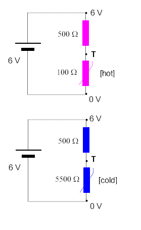
The top resistor has the same value in a hot environment as in a cold one, but the thermistor changes resistance according to the ambient temperature.

In the top diagram, the thermistor is hot and has a lower temperature than the fixed resistor. This means that, since the thermistor only has one sixth of the total resistance, it only has one sixth of the total p.d. So the potential at T is 1 V.

When the temperature drops, however, the thermistor's resistance rises, so that it now has eleven twelfths of the total. Hence the p.d. across it rises to eleven twelfths of the total p.d. So the potential at T rises to 5.5 V.

This rising potential can be made to do something useful, like switching a heater on. It would be necessary to have some kind of amplifier and/or a relay connected between T and the chassis (the 0 V line), because the currents in this part of the circuit are necessarily low.


The potentiometer

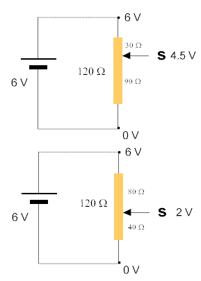
A potentiometer is a resistor with a sliding contact dividing the resistor into two parts. Sometimes is it circular in shape, sometimes linear. You can even get ones which may be thought of as essentially spiral, in which you turn a dial round ten times to get the slider from end to end. Called 'ten-turn pots', they have an accurate scale enabling you to tell just how far along the slider is to within 0.1%.

The slider divides the resistor up into two sub-resistors in series. In the top diagram, S is three-quarters of the way from the 0 volt end, so you effectively have a 30 W resistor and a 90 W resistor in series. Applying the usual rules, three-quarters of the available p.d. is across the 90 W portion, so the potential at S is 4½ V.

Similarly, the slider is a third of the way up in the lower diagram, so that the pd across S and chassis is a third of the total, making the potential at S equal to 2 V.


The bridge circuit

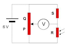
Suppose that the slider on the potentiometer is half way along the track, so that resistances Q and P are the same. We may deduce that the potential at the left hand side of the voltmeter is 3 V since P is half of the total resistance (P + Q).

Suppose, further, that the voltmeter gives a zero indication. We may deduce that the potential at the right hand side of the voltmeter is also 3 V, since the meter has told us that there is no p.d. across its terminals.

Since we now know that the potential between S and R is half of the overall 6 V, we may deduce that R is half of the overall resistance (R + S), and that R and S are equal.

Extending this particular case to the general case, we can easily show that when the voltmeter reads zero it is true that P/Q = R/S.

So we make strenuous efforts not to let S change. Then, for any particular value of R which we wish to determine, we adjust the slider until the meter reads zero, find what fraction of the way along the track the slider is, and argue that that fraction is equal to R/(R + S). Hence we can calculate R.


Tony Ayres, March 2001