The point about this effect is that if light were essentially unlocalised and continuous, then shining it onto a metal surface would bathe all of the electrons with equal energy. All would gradually become more excited until suddenly all the electrons would simultaneously have acquired enough energy to escape from the metal at once. If you had dim light, you'd have to leave it on for longer, but there'd be no problem with that. Furthermore, in such a scenario, the ejected electrons would have no surplus energy.
If, on the other hand, light were particulate, at any rate to the extent of being highly localised, then an individual light 'particle' could, if it were energetic enough, eject an electron as soon as it struck the metal. Under these circumstances, you would get a current proportional to the light intensity. It was already part of standard theory in the pre-quantum era that high frequency oscillators possessed more energy than low frequency oscillators, so you would expect violet photons to be more energetic than red photons. So, then, on this model, red light would eject no electrons at all, there would be a colour at which the effect would kick in and, lastly, violet light would leave a particular quantity of energy over for each ejected electron to take away with it: increasing the light intensity would increase the number of electrons escaping, but wouldn't affect the energy each carried off.
The experiments bear out all the predictions of the second paragraph but none of the first. The experiment therefore makes the particulate theory seem the more attractive option.
Three experiments are on offer, one of which is illustrated opposite.
(Actually, it's a bit more complicated than this, because you might find yourself with an energy level model of atoms even if light could be radiated continuously (i.e. not in photons) from freely oscillating electrons in the source. In that case electrons in the target wouldn't be able to 'save up' the incoming energy even if they wanted to, and they would have to accept it in lumps. But it would still be true that if sufficiently intense long wavelength (red) light were incident, the energy on one electron could be enough to eject it, but the ejection would happen instantaneously once the threshold intensity had been passed. But this is not observed. It is no use trying to provide the energy with bright red light. It's got to be violet, and then it can be as dim as you please.)

This diagram shows the basic idea. Photons release electrons from the cathode, leaving them with some spare energy. The electrons drift towards the anode - when they get there, they return to the cathode via the ammeter. But the anode is connected to the negative terminal of a variable cell (unusual for an anode!), and this tends to repel the electron. When the cell voltage is just right, the electrons are just prevented from reaching the anode, and the current falls to zero (the diagram shows one electron just being turned round before reaching its goal). In this way, we can measure the energy of the emitted electrons.
In practice, the circuit is a little more complicated. Variable cells are not available in electronics catalogues, so we have to engineer the effect with a potentiometer.
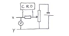
This circuit replaces everything to the right of the XY line in the top circuit. You will notice that the current detecting arrangement is different, too as it is detected by the pd it produces when flowing through a resistor. What we do is to illuminate the photo-emitting surface with light from an AC-driven bulb, so that the intensity varies at 100 Hz. This means that the photo-current varies at 100 Hz, and we can use the CRO's amplification system to make it easily detectable.
By using different filters and finding the value of V required to flatten the AC trace on the CRO (draw pictures?), you can draw a graph of qV (q= electron's charge) against f. It has the equation qV = hf - f0 , which may be interpreted as
residual energy = energy provided by the photon - energy needed to escape from the Fermi sea (called the 'work function').
The residual energy is kinetic energy, and is available to 'fight' the electric field produced by the negative voltage, which is attempting to push the electrons back to the potassium surface. So the slope gives Planck's constant.
Photomultiplier tubes in gamma cameras, which are able to produce a measurable current by amplifying the effects of the ejection of just one electron by a gamma ray (or X-Ray).
[diagrams may appear later]
[diagrams may appear later]
We're pretty clear that electrons are normally in essence localised and particulate. If we see a ring of green on the face of a CRT we imagine that someone has made a beam of electrons and then applied clever AC potentials to the X and Y plates to make the beam deflect differently at different times to give the illusion of a circle. It is disconcerting to look at the tube and find that there are no deflection plates and that the rings in question have the fuzzy appearance we associate with interference fringes.
A way coping with the situation is to say that there is an abstract 'nothing actually there' wave - an 'instruction wave', I sometimes say - and that this wave treats the graphite flakes as a lots of randomly oriented diffraction gratings that produce conical maxima, and that the electrons then, one by one, 'decide' to go in some direction or another with a probability proportional to the square of the amplitude of the instruction wave (sometimes called a 'guiding wave').
[diagrams may appear later]